
The Core is the centralized digital signal processor (DSP) for the Q-SYS system.
There are three aspects to the Core: physical hardware, network settings, and virtual.
The Inventory list in Q-SYS Designer always has a Core listed. All other Inventory components can be in the design, or not. Each Core has a number of components listed under the Core in the Inventory list. You place these components in your design as required. The components listed under the Core may differ depending on the Core Model you select.
The GPIO, Loudspeaker Monitor, Serial Port, and the I/O cards (Line Out, Mic/Line In, DataPort, AES3 In / Out, AES3 16 Channel In, AVB In / Out, Cobranet In / Out, and Dante In / Out, are documented their individual topics.
The Core 110f has separate topics for: Mic/Line In, Mic/Line Out, USB In, USB Out, Flex In, Flex Out, POTS In, POTS Out, POTS Controller, GPIO In, GPIO Out. The controls available only on the Core110f are indicated as such in this topic.
QSC currently offers the Core models listed below.
NOTE: For more information on NACs and NASs, refer to Networked Audio Design.
When you start Q-SYS Designer the Inventory accordion bar, in the left-side pane, is open by default. Under Inventory, by default, a Core is present. The Core is in the Default Location, and has components listed below it. The components may differ depending on the Core Model selected.
Select the Core. The Core Properties display in the right-side pane. If you drag the Status component into the Schematic, the same properties are displayed in the right-side pane, with the addition of the available Control Pins for the Status component. This topic contains information for both.
NOTE: Click the link to jump to the Properties and Control Pins tables below.
Type 2 hardware provides new cables and connectors between the I/O cards and main boards in Cores and I/O Frames. Due to this change, the Type 2 hardware is not physically compatible with the older hardware. You can still integrate the new I/O Frames and Cores in the same system with older hardware, but the I/O cards are not interchangeable. Type 2 hardware can be identified by a yellow label on the back of the Core and I/O Frame, and the bottom of the I/O cards.
Some controls require a specific setting in the Properties. In the Properties Settings column
R represents Is Redundant set to Yes
V represents Verbose set to Yes
C represents the Clock Source set to something other than Internal
N represents Not available on all Cores
|
Control |
Function |
Default/Range |
Properties Setting |
||||||||||||
|---|---|---|---|---|---|---|---|---|---|---|---|---|---|---|---|
|
ID |
When the ID/Identify button, in the Q-SYS Designer Status component, or the Configurator's Network Configuration for the hardware, or on the physical hardware is pressed, the ID buttons in the Configurator and Status component flash, and the LCD on the physical Hardware flashes to indicate the association between the three. The indicators will flash for 5 minutes unless you stop them by pressing any one of the buttons. |
Off/On |
N/A |
||||||||||||
|
Status LED |
This LED changes color to indicate the current status of the Core. See Status for the meanings of the various colors. |
N/A |
N/A |
||||||||||||
|
Status |
Displays color-coded messages indicating the current status of the active Core. OK – Green – (0) – Audio is good, hardware is good. Compromised – Orange – (1) – Audio is good but a redundancy mechanism is active (one LAN down but the other is still up) or a non-fatal hardware problem exists (fans too slow, temperature higher than expected, etc.) Fault – Red – (2) – Audio is not passing, or hardware is malfunctioning or mis-configured (amplifier power off, audio streams broken, wrong type of I/O Card installed, loudspeaker short circuit, etc.) Missing – Red – (3) – A piece of hardware, defined in the design, has not been discovered. Audio is not passing through that piece of hardware. Initializing – Blue – (5) – In the process of firmware, configuration update, and design start. Audio is obviously bad. Not Present – Gray – A virtual component in the design, that is designated as Dynamically Paired, and Not Required ,has no hardware assigned to it. |
N/A |
N/A |
||||||||||||
|
External Clock |
The Clock Source in the Core's Properties must not be set to Internal. The External Clock illuminates if the Core receives a valid external word clock or AES3 signal. |
Off/On |
C | ||||||||||||
|
External Frequency |
The Clock Source in the Core's Properties must not be set to Internal. The frequency of the clock sync connected to GPIO. This is usually 48000 (+- a few samples). If you are using GPS sync it will be either 5 (for 5pps) or 1 (for 1pps) |
|
C | ||||||||||||
|
External Lock |
The Clock Source in the Core's Properties must not be set to Internal. The External Lock illuminates if the Core is able to successfully synchronize to the external clock signal. |
Off/On |
C | ||||||||||||
|
Clock Master |
LED indicating if the Core is the Master Clock for the Q-SYS system or not. The Core can be the Master Clock even if the clock is synchronized to an external clock. |
Off/On |
N/A |
||||||||||||
|
Clock Offset |
Indicates how much of an offset exists between this Core and the Master Clock. If this Core is the Master Clock, the offset is zero. |
No default Microseconds |
N/A |
||||||||||||
|
Grandmaster |
The clock master of the network. See ( http://en.wikipedia.org/wiki/Precision_Time_Protocol#Architecture) |
N/A |
N/A |
||||||||||||
|
Parent Port |
The device and interface name that this device is syncing to when it’s not the clock master. Usually it is the same as the Grandmaster name. |
N/A |
N/A |
||||||||||||
|
Processor Temp |
The current temperature, in Celsius, of the Core processor. |
N/A |
N/A |
||||||||||||
|
Chassis Temp |
The current temperature, in Celsius, of the Core chassis. |
N/A |
N |
||||||||||||
|
Memory Used |
The percentage of memory used. |
N/A |
V |
||||||||||||
|
Chassis Fan |
The current speed of the chassis fan in RPM. The speed varies based on the temperature. |
N/A |
N |
||||||||||||
|
Processor Fan |
The current speed of the processor fan in RPM. The speed varies based on the temperature. |
N/A |
N |
||||||||||||
|
Audio File Sync |
Text field indicating whether or not the audio files on the inactive Core of a redundant pair are in sync with the active Core. |
N/A |
R | ||||||||||||
|
Details |
You must select Verbose Yes in the Properties for this field to display. Text indicating the Details of any errors occurring with the Core. The information in this field is updated regularly and is cumulative. None of the items listed below display unless there is a value associated with it. If there are values associated with these, call QSC Technical Support.
|
N/A |
V |
This section is available only when the Is Redundant Property is set to Yes.
|
Control |
Function |
Default/Range |
|---|---|---|
|
Active |
Identifies which Core is currently Active |
On/Off |
|
Standby |
Lights if the Core is in Standby mode. When the Core is booting, this LED is lit. |
Off/On |
|
Go Active |
Click this button to force the inactive Core to become Active. 1 |
Off/On |
1. In a redundant Core, redundant network system when the LAN-A connection to one Core is removed, and the LAN-B connection to the other Core is removed, you cannot switch between Cores using the Go-Active button. |
||
This section is available only when the Verbose Property is set to Yes.
|
Control |
Function |
Default/Range |
|---|---|---|
|
Audio (audio processing time - microseconds) |
Contains the following information when the count is not zero:
|
N/A |
|
Reset |
Resets the statistics in the Audio and Network fields. While the Reset button resets all entries in both fields, the average, periods, and overruns are the most noticeable. |
Momentary switch |
When you create a design in Q-SYS Designer you do so in the Design Mode. This is the default mode when you start Q-SYS Designer. During the course of creating your design you can save the design to your PC's hard drive, Emulate the design, or save the design to the Core and run it. When a design is Emulated, a Core is not required; you can Emulate on your PC. When you save the design to the Core and run it, your PC must be connected to a Core via the Q-SYS network, and the Core to which you are connecting must be identified in your design, per this topic.
Below are a few scenarios you may encounter while working with Cores and Designs.
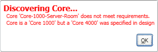
When you specify the Core model in the Core Properties of your design, the physical Core model must be equal to or greater than the model you specify in the Properties or the design will not run and Q-SYS Designer displays the following error:
If you named and saved the design on your PC, then "Save to Core & Run", the design is saved on the Core with the same name including all its current Control settings. If you have not save the design on your PC, and Press F5 (Save to Core & Run) a design file named "untitled" is saved on the Core with all its current Control settings. If your Core is connected to live audio output, any control setting changes have an immediate impact on the output.
While a design is running on the Core, and open in Q-SYS Designer, if you Press F7 (Disconnect) Q-SYS Designer is disconnected from the Core and you can make changes to the design. The design you saved on the Core is still running on the Core - unchanged. If you make design changes to the design and Save to Core & Run (F5), the design on the Core is overwritten and restarted with the new changes and/or Control settings. If your Core is connected to live audio output, any control setting changes have an immediate impact on the output.
If you are working on a design and choose File > Load from Core & Connect..., a new instance of Q-SYS Designer is started on your PC and the design currently running on the Core is loaded into the second instance of Q-SYS Designer in the Run mode. The design on the Core is not restarted, it merely continues running as it is loaded into Q-SYS Designer. You can now make changes to the Control settings, but not the design (with the exception of Control Scripts). The design you were working on in the first instance of Q-SYS Designer is not affected.
IMPORTANT: If you are working on a design that is saved on your PC, then load a design with the same name from the Core and run it in a new instance of Q-SYS Designer, then try to save that design on your PC, you are presented with a "Save As" dialog. This gives you the opportunity to either rename the design as you save it, or overwrite the design saved on your PC - the one on which you were working. Caution is recommended in cases like this! At this point, you have two instances of Q-SYS Designer open; the first is in Design mode, the second is in Run mode. They have the same design file name. If you made design changes to the design in the first instance, then overwrite the file on your PC with the one running on the Core, you just lost the changes you made in the first instance. If you still have the first instance open, the changes you made are in that open file, and you can overwrite the file on your PC again - this time it does not present you with a "Save As" dialog, it just overwrites the file.
If you save a design in one version of Q-SYS Designer, then upgrade Q-SYS Designer software and attempt to open the file, you are presented with the following message:
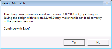
Refer to the release notes to determine compatibility. It is also important to consider other people that may be working on the same design file.
If a design was saved in one version of Q-SYS Designer and you attempt to open it with an older version of Q-SYS Designer, you are presented with the following message:
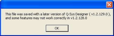
It is recommended that you upgrade the Q-SYS Designer software on your PC. Click for Software Updates
You can only have one design on the Core at a time. If a design is running on the Core, and you are working on a different design on your PC, then press F5 (Save to Core & Run), the design running on the Core is stopped, and your design is loaded and starts running. You cannot retrieve the first design from the Core. If it was saved on a PC with Q-SYS Designer, you can re-load it from there.
If a design is running on a Core, and the Core loses power, or is rebooted, the design running when it lost power is restarted.
Once a design is finished, loaded onto a Core and run, you may disconnect the PC running Q-SYS Designer. The design continues to run on the Core and can be used as designed without Q-SYS Designer.
|
Property |
Function |
Choices |
|---|---|---|
|
Name |
Identifies the Core component in Q-SYS Designer, enabling the connection between the design and the physical Core. This name should be the same as the Core Device Name (hostname) in the Configurator. Click in the Name property and type the Name. The name must follow standard naming conventions. The Administrator restricts the name according to the following: ASCII characters a - z, A-Z (case insensitive) Digits 0 - 9 Hyphen (cannot be at the beginning or end of the name) Underscore (acceptable with a Q-SYS implementation) No other characters, symbols, punctuation, or blank spaces. When you have entered the Name, it displays next to the Core icon in the left-side pane. Note: When you use Telnet or 3rd party external control you must enter the Name exactly as it is entered here. |
User input |
|
Location |
The Location is a means by which you can organize your virtual equipment to correspond to your physical equipment. For example, the Core may be in Rack 1.
When you have given the location a name, the Core is now displayed under the new location. Any other equipment you identify as being in that location display under that location. |
User input |
|
Model |
Select the model to match that of the physical Core. The model of your physical Core must be equal to, or greater than what you specify in this Property or the design will not run. |
250i 500i 1000 1100 3000 3100 4000 |
|
Is Redundant |
If you have redundant Cores in the installation select Yes, otherwise, leave it as No. |
No / Yes |
|
USB Endpoint Count |
Available on the Core 110f only The number of USB Endpoints you want in your design. You can have 1 to 4 Endpoints. Each Endpoint has an Input component, and an output component. This property can be set from any of the Core's components. |
1 to 4 |
|
Backup Name |
This property displays when you set Is Redundant to Yes. Same as the primary Core Name. |
User input |
|
USB Endpoint Properties |
Refer to the USB Out and USB In topics for properties specific to the USB components. Available only on the Core 110f. |
N/A |
|
Telephone Country |
Select the country in which the telephone service resides. Available only on the Core 110f. |
Listed alphabetically from Argentina to Yemen |
|
Tone Output |
When Yes is selected, the Ring/Entry/Exit/DTMF tones are fed to a new output channel (Tone Output) on the POTS Input component. These tones are now separate from the voice audio. Available only on the Core 110f. |
No / Yes |
|
I/O Slot |
Identifies the type of I/O card installed in the physical Core. When you have selected this property, your selection displays under the Core in the Inventory list. Not available on the Core 110f. |
|
|
AES3 - SRC Disabled |
When an AES3 In / Out or AES3 16-channel In card is selected for the I/O Slot Property, you have the ability to disable or enable the AES3 Sample Rate Conversion. Not available on the Core 110f. |
Enabled / Disabled |
|
Specifies the total number of audio tracks any Audio Players placed in the design are allowed to play based on options you purchase. If the Core does not have the appropriate options installed, and you choose a number of tracks greater than the installed option maximum, the design will not compile. |
Default = 16 Range = 16, 64, or 128 |
|
|
Network Receive Buffer |
Adds extra buffer time to the default maximum of 1 ms. Additional Network Receive Buffer time is useful in (rare) cases where the network latency through the network exceeds the default maximum. Additional network latency my be introduced by sub-optimal QoS functionality, some layer-3 routing implementations, long distances or large networks. Because the specified additional latency is added both to transfers from IO Frames to the Core and from the Core to IO Frames, the additional system latency is twice the amount of additional receive buffer selected. Total system latency based on this setting is calculated and displayed immediately below the Network Receive Buffer property. |
Default Extra 1/3 ms Extra 1 ms Extra 2/3 ms |
|
Property |
Function |
Choices |
|---|---|---|
|
Sample Rate |
Selects the sample rate. Typically, 48kHz is used as the Sample Rate. In scenarios where Q-SYS is externally synchronized to a (video) house sync signal you would use 48kHz Pull Down as the Sample Rate. |
48 kHz 48 kHz Pull-Down |
|
Clock Source (All Cores except the Core110f) |
The AES3-1 and AES3-2 options display when you have an AES3 In / Out card selected for the Core I/O slot. When you have an AES3 16-channel In card selected, only the AES3-1 option is available. Use these options to sync to an external AES3 signal. The AES3 selections require either regular AES3 or AES3 black. The clock should be connected to the AES3 card either connector Channel 1/2 In, or Channel 3/4 In. The GPIO selections require an external TTL level word clock or a GPS connection: pin 3 is signal, pin 8 is ground. When you select GPIO A-1 or GPIO B-1 as the clock source, the respective GPIO 1 Property changes to "Input used as clock source". The clock source should be connected to pin 3 of the respective GPIO connector - either GPIO A or GPIO B. NOTE: Typically, Internal is used as the clock source. Only if there is a need to synchronize the Q-SYS system to an external clock would you use GPIO or AES3. You would use GPIO if the external clock signal is a word clock or GPS. You would use AES3 if the external clock signal is an AES3 signal. Often an AES3 signal without audio is used to reduce the clock jitter. This signal is called AES3 black. |
AES3-1 AES3-2 GPIO A-1 GPIO B-1 Internal |
|
Clock Source Core 110f |
The GPIO selection requires an external TTL level word clock or a GPS connection: pin 1 is signal, ground in indicated by the ground symbol on either end of the connector. When you select GPIO In Pin 1 as the clock source, GPIO Pin 1 is no longer displayed. The clock source should be connected to pin 1 of the GPIO connector. |
Internal GPIO In Pin 1 |
|
Clock Type |
The type of the source clock. GPS requires a connection to a GPS Receiver, Word Clock requires TTL level word clock. |
GPS (1 PPS) GPS (5 PPS) Word Clock |
|
Default (0) – the predefined clock domain number 0 (zero). Alt 1 (1) – Alt 3 (3) – the predefined clock domain numbers 1 through 3. User (4–127) – the user-selected clock domain numbers 4–127 Cores using the same name are synchronized to the Core Master. Synchronizing the Cores is required to use LAN Streaming between Cores. |
Default (0) Alt 1 (1) Alt 2 (2) Alt 3 (3) User (4–147) |
|
|
PTP Priority |
Priority is used to select the clock master for a given domain. It maps to the ‘Priority 2’ property in the ‘Best master clock algorithm’. Devices with a lower numeric value for Priority will be selected over a device with a higher numeric value. In other words – 0 is the highest priority and 255 is the lowest priority. |
0 to 255 |
|
Verbose |
Adds CPU Statistics Audio and Network to the Core Status component, along with a Reset button to reset the statistics to zero. |
Yes / No |
There are no Control Pins available for the Core when it is selected in the Inventory list. The Control Pins are only available for the Core Status component when it is in the Schematic. The available Control Pins depend on settings in Properties.
|
Pin Name |
Value |
String |
Position |
Pins Available |
|---|---|---|---|---|
|
(Primary/Backup) Active |
0 1 |
false true |
0 1 |
Output |
|
(Primary/Backup) Go Active |
0 1 |
false true |
0 1 |
Input / Output |
|
(Primary/Backup) Standby |
0 1 |
false true |
0 1 |
Output |
|
Chassis Fan RPM 1 |
4-digit number |
text |
N/ A |
Output |
|
Statistics - Audio 1 |
Text box with statistics on the audio on network 1 |
Output |
||
|
Statistics - Audio 2 |
Text box with statistics on the audio on network 2 |
Output |
||
|
Statistics - Reset |
trigger |
Input / Output |
||
|
Audio File Sync |
Text box with information regarding syncing audio files between redundant Cores |
Output |
||
|
Chassis Temperature |
Text box displaying the internal temperature of the Core in Centigrade. |
Output |
||
|
Core Status |
0 1 2 3 4 |
OK (green) Compromised (orange) Fault (red) Unknown (red) Updating (blue) |
0 0.250 0.500 0.750 1.00 |
Output |
|
External Clock |
0 1 |
false true |
0 1 |
Output |
|
External Clock Frequency |
Text box displaying the external clocks frequency in Hz. |
|||
|
External Lock |
0 1 |
false true |
0 1 |
Output |
|
Identify |
0 1 |
false true |
0 1 |
Input / Output |
| Memory Used | 0 to 100 |
Text 0 to 100% |
0.0 to 1.00 |
Output |
| Network Clock Grandmaster Name | Text box indicating the network name of the Network Clock Grandmaster |
Output |
||
|
Network Clock Master |
0 1 |
false true |
0 1 |
Output |
|
Network Clock Offset From Master |
0.000 to n |
0 ms to n ms |
0 to 1.000 |
Output |
|
Network Clock Master |
0 1 |
false true |
0 1 |
Output |
|
Network Clock Offset From Master |
0.000 to n |
0 ms to n ms |
0 to 1.000 |
Output |
|
Network Clock Parent Port Name |
Text box indicating the network name of the Parent port, usually the same as the Network Clock Grandmaster with the LAN appended. |
Output |
||
|
Processor Fan RPM |
4-digit number |
text |
N/ A |
Output |
|
Processor Temperature |
Text box displaying the temperature of the Core's processor in Centigrade. |
Output |
||
1. For Cores 110f, 250i and 500i only. |
||||
© 2009 - 2016 QSC, LLC. All rights reserved. QSC and the QSC logo are trademarks of QSC, LLC in the U.S. Patent and Trademark office and other countries. All other trademarks are the property of their respective owners.
http://patents.qsc.com.
![]()
 Related Topics